Design positions based on available space and stored objects. These use hypotheses can be checked against user records.
SCENARIOUSER NEEDDESIGN RESPONSE
01
Compact courtyard
Limited outdoor space; a place for everyday tools.
Need
A compact footprint, easy access and edge placement.
Response
Single slope · Simple profile and focused access
02
Equipment storage
Larger gardening equipment needs space to move.
Need
Consider entrance width, internal height, light and ventilation.
Response
Gable · Raised centre and double-door approach
03
Storage + shelter
Combine enclosed storage with sheltered parking or rest.
Need
Arrange open and enclosed areas for different activities.
Response
Combined canopy · One roof linking two uses
02 / PRODUCT DESIGN MATRIX
Three product proposals
A shared language of panels, frames and openings supports different roofs and spatial combinations. Explore each form through its use, composition and design priorities.
Compact space / Edge placement
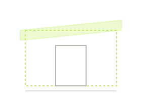
Single-slope shed
A single roof slope keeps the form simple and explores storage along garden boundaries and in narrower spaces.
Use scenario
Everyday garden tools and smaller equipment.
Form & openings
One roof slope and a focused entrance, with optional high-level daylighting.
Design priorities
Manage the footprint, drainage, edge junctions and access route.
Concept diagram · Not a construction drawing
Larger storage / Internal height
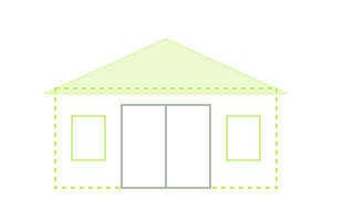
Gable shed
A raised roof centre shapes the interior, while double doors and side openings establish a clear façade arrangement.
Use scenario
Gardening equipment, larger tools and storage that needs room to move.
Form & openings
Gable roof, central double doors, with light and ventilation openings.
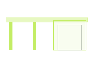
Combine a shed with open covered space, using a continuous roof to link storage, parking or a place to pause.
Use scenario
Combined needs for tool storage, small-equipment parking and outdoor rest.
Form & openings
An enclosed body alongside open posts, with access oriented toward the canopy.
Design priorities
Organise open and enclosed zones; review joints, spans and drainage next.
Concept diagram · Not a construction drawing
Sheds & pet houses · Five product forms +
Gable-roof shedView detail +Single-slope shedView detail +Shed with canopyView detail +Small single-slope pet houseView detail +Small gable-roof pet houseView detail +
03 / MATERIALS & ENGINEERING DETAILS
Materials & structural components
Six component groups organise the choices for wall panels, frames, roofing and openings. These include proposed materials; specifications and performance remain subject to confirmation.
Wall assembly
Exterior cladding options
Exterior cladding can use standard WPC wall panels, fluted WPC panels or ASA WPC panels, balancing appearance and budget. In this project’s material comparison, ASA WPC offers the best visual finish at the highest cost.
Roofing options include epoxy resin tiles and ASA wall panels. Epoxy resin tiles suit most scenarios, while ASA wall panels suit smaller sheds. Select according to shed size and overall appearance.
Options
Epoxy resin tiles / ASA panels
To verify
Fixing, drainage & performance
Epoxy resin roof tilesASA wall panel
Frame connections
Aluminium connection system
Map the assembly of three-way posts, corner posts, opposed-channel posts, U-channels and base rails to explore shared interfaces across forms.
Components
Posts / Base rails / Edges
Interface goal
Coordinate with panel joints
Three-way aluminium postCorner aluminium postOpposed-channel aluminium postAluminium U-channelAluminium base rail
Beam & post layout
WPC beams & profiles
Use existing profiles to explore support layouts and frame proportions for the shed and canopy. Loads and spans require engineering review.
Foundation preparation comes before frame assembly, door/window adjustment and everyday use. Six checks cover ground conditions, levels, structure, dimensions, drainage and site services.
Foundation and shed footprint · Supplied reference diagramView detail +
Foundation preparation reference
The following summarises supplied installation information; use the project’s confirmed engineering documents for execution. Original image annotations are retained. Check support-surface levels and surrounding drainage slopes as separate zones.
01
Ground conditions
Hardstanding & sub-base
Prioritise concrete hardstanding. Check the reinforced sub-base beneath tiles or timber platforms; assess hardening, levelling and settlement conditions for soil or lawn sites.
02
Level checks
Level deviation ≤ 3 mm/m
The supplied reference limits support-surface level deviation to 3 mm per metre. Check each point with a level, focusing on frame supports to manage uneven door/window gaps and assembly misalignment.
03
Strength & thickness
C25 · ≥ 10 cm
Supplied reference: concrete grade C25 or higher, at least 10 cm thick. A 15 cm slab with reinforcement mesh is proposed for longer spans or heavier loads; confirm thickness and reinforcement for the site and loads.
04
Dimensions & clearance
+15 cm each side · Diagonal difference ≤ 5 mm
Allow 15 cm beyond each side of the shed base footprint for installation and maintenance. The supplied reference limits the difference between diagonal lengths to 5 mm for checking squareness and frame alignment.
05
Drainage layout
Surrounding drainage slope 1%–2%
Avoid low-lying, flood-prone locations. Distinguish the level support surface from surrounding outward drainage. Use the supplied 1%–2% slope as a reference for the surrounding drainage area; confirm zones, levels and flow paths through engineering review.
06
Site services
Clearance · Services · Earthing
Clear the site and reserve planned water and electrical service connections. Where lightning protection and earthing are required, coordinate them with the electrical design and verify connections to foundation reinforcement.
05 / REGIONAL ADAPTATION
Regional adaptation concepts
After defining forms and components, compare configuration trade-offs for different market directions. These are design concepts, not local research findings or delivered project outcomes.
Europe & North America
Design & experience
Garden aesthetics / Choice / Self-assembly
Priorities
Garden appearance, usable space and self-assembly information.
Configuration
Explore woodgrain and frame colours, with door, window and roof options.
Design trade-off
Balance visual consistency, choice and clear assembly instructions.
Sun, seasonal rain, ventilation and configuration cost.
Configuration
Explore ventilation and drainage with a simpler accessory selection.
Design trade-off
Prioritise use requirements, then manage accessory count and configuration complexity.
Actual weather conditions, use patterns and structural requirements need further review. The next section demonstrates configuration differences through a simulation.
06 / CONFIGURATION STUDY
BOM & budget demonstration
An interactive version of the proposal’s simplified model, showing how form, dimensions and options affect estimates.
SIMULATION ONLY · Demonstrates configuration logic; not an actual BOM, loading plan or quotation.
SIMULATED OUTPUT / NOT PRODUCTION DATA
Wall area m²
Aluminium length m
Roof area m²
40HQ loading sets
Model estimate · USD / set
Container quantities are fixed demo values by form and do not change with dimensions. Canopy roofing assumes an additional 2.5 m width; this is not an engineered size specification.
View simulation assumptions +
The supplied proposal’s simplified model: wall area = perimeter × 2.1 m, without subtracting openings; roof area = width × depth × 1.15, or (width + 2.5) × depth × 1.1 for the canopy; aluminium length = (width + depth) × 4 + 10.
Model amount = wall area × configuration factor (65 / 42) + roof area × 35 + 200; add 450 for a canopy, 120 / 60 for openings, and 45 for a lock. Areas are rounded to one decimal place; the final amount is rounded to the nearest ten. Fixed loading examples are 60, 45 and 22 sets for single-slope, gable and canopy forms. All factors are illustrative, not supplier prices or shipping calculations.